Battery Management, Connectors Key to EV/HEV Performance
by Bill Schweber for Mouser Electronics
Featured Products
Featured Manufacturers
Related Resources
Electronic engineers involved with electric vehicles (EV/HEV)
generally have to work with the available battery technologies, which are usually some variant of lithium-ion based
chemistry. However, they do have a significant challenge in managing the large assembly of cells which comprise the
battery packs. The battery management system (BMS) which designers implement has three major objectives:
- Protect the individual cells and the complete battery assembly from damage
- Prolong the life of the batteries
These objectives translate to a lengthy list including functions such as cell protection, charge control, state of
charge determination, state of health determination, and cell balancing. This article looks at one of the BMS
functions - cell balancing - which is representative of the intense challenges that EV/HEV designers must address.
The reality of the overall EV/HEV design is that all BMS issues are interrelated to some extent rather than isolated
(see Figure 1.) Therefore, there is a "ripple effect" as the battery condition or status changes
and the BMS deals with them. One of the objectives of the BMS architecture is to separate these subfunctions to the
best extent possible, so each one can be independently optimized and so contribute to a globally optimized design.
Figure 1: The EV/HEV power system, of which the battery management is a major
subsystem, is an extremely complex arrangement involving hardware, software, and battery chemistry which involves
many tradeoffs and judgments related to both "normal" operation as well. (Image: Maxim Integrated, "The Automotive
Experience.")
Further, as in most engineering decisions, there is no single "right" way to achieve a given goal. Each approach
brings tradeoffs among factors of size, packaging, replaceable units, weight, data integrity, system confidence, and
cost. The decision also depends on the objectives: longest range, longest battery-pack life, tolerance of weakness
in individual cells in a pack, and safety, of course, to cite a few. The "best" solution is therefore dictated by
the design priorities.
Cell Balancing: a Complex Issue
An unavoidable fact is that in multi-cell battery chains, there will always be small differences between cells due
to production and operating conditions (especially temperature gradients, which can be significant for large battery
packs).These differences are magnified with each charge/discharge cycle, with weaker cells becoming even weaker
until they eventually fail, and cause premature failure of the larger battery pack.
Cell balancing compensates for weaker cells by attempting to equalize, or balance, the charge on all the cells
within the pack. Various methods of cell balancing have been developed to address this problem. The approach is also
a function of the battery chemistry: lithium-based batteries are more tolerant of the "micro" charge/discharge
cycles associated with HEVs, but they are more affected by cell-to-cell differences. In contrast, there is some
natural cell balancing by increasing the charging time with lead acid and NiMH cells, since the fully charged cells
will release energy by out-gassing until the weaker cells reach their full charge.
The two most-common cell-balancing techniques are active and passive balancing; other approaches, such as charge
shunting and lossless balancing are also used but, as always, there are difficult tradeoffs. Both start by
monitoring the state of charge (SOC) of each cell. It is measured by "coulomb counting" of current flow into and out
of the battery, sometimes supplemented by a battery-impedance measurement. In some situations, only the voltage
across each cell is measured. Switching circuits then control the charge applied to each individual cell in the
chain during the charging process to equalize the charge on all the cells in the pack.
In active balancing, charge is removed from higher-charged cells and passed to lower-charged cells. This is a
time-consuming process since it must be done by assessing each cell in what may be a very large number (hundreds and
thousands). Some active cell-balancing schemes are designed to stop charging a cell which is fully charged and
continue charging the weaker until they reach full charge, thus maximizing the battery's charge capacity.
In passive balancing, excess energy in higher-charged cells is automatically drained through a bypass resistor until
the voltage or charge matches the voltage on the weaker cells. It is a low-cost option but wastes energy in the
bypass resistors, and also bounds battery-pack performance by the weakest cells. Regardless of method used,
squeezing out the last percentage points of capacity and performance will add greatly to BMS system complexity, BOM
size, hardware size and cost, and software integration issues.
Targeting this BMS and cell-balancing challenge, the Maxim
Integrated MAX14920
and similar MAX14921
battery measurement analog front-end (AFE) ICs accurately sample cell voltages for battery packs up to 16
cells at up to +65 V (the MAX14920 handles up to 12 cells, while the otherwise-identical MAX14921 is for 16 cells,
see Figure 2.) The devices simultaneously sample all cell voltages for accurate state-of-charge and
source-resistance determination, a time-saving feature for larger packs. All cell voltages are level-shifted to a
ground reference at unity gain, which greatly eases the data-conversion ranging for the external analog/digital
converter (ADC).
Figure 2: The Maxim MAX14920 and similar MAX14921 cell-measurement analog
front-end (AFE) ICs are designed to simplify the critical task of cell balancing among the many battery cells
which comprise the battery packs. (Image: Maxim Integrated)
Passive-cell balancing is supported by external FET drivers. Integrated diagnostics in the ICs allow open-wire
detection and undervoltage/overvoltage alarms, for additional system integrity. The BMS devices are controlled by a
daisy-chainable SPI interface, so they can be connected, addressed, and managed via a single SPI port. The SPI
control can select the readout of any cell voltages, in any order (Figure 3).
Figure 3: The cell-balancing function of the BMS can use the SPI control of
the Maxim MAX14920/MAX14921 to select the readout of any cell voltages, in any order. (Image: Maxim
Integrated)
Accuracy is an issue with battery-cell monitoring, especially with chemistries which have fairly flat discharge
curves. The high accuracy of these Maxim ICs makes them a good fit for cell chemistries with very flat discharge
curves, such as lithium-metal phosphate. Their low-noise, low-offset amplifier buffers any differential voltages of
up to +5 V, allowing monitoring of all common lithium-ion (Li+) cell technologies.
Combined with the internal self-calibration feature, the resulting cell voltage error is ±0.5 mV. The Maxim ICs
are specified over the -40°C to +85°C extended temperature range, a necessity for the EV/HEV operating
environment.
Don't Ignore Connections and Amperes
For engineers whose exposure to "high power" is limited to a few hundred watts or under ten amps, the world of
EV/HEV power interconnection needs a very different mindset. EV/HEV designs inherently deal with large flows of
current between the various subsystems and assemblies, and at high voltages. Designers must select wire-to-board and
wire-to-wire connectors which meet challenging criteria for power-handling, insertion/removal cycles, and mechanical
ruggedness under very difficult conditions of vibration, stress, and temperature. As a result, there are unique
considerations for power connectors associated with the battery subsystem. There can be no "cutting corners" or
"we'll worry about that later" attitudes when dealing with these high-current/voltage issues in the EV/HEV
environment-they must be an early, prominent part of the design process.
Phoenix Contact's
E-Mobility Solutions are an example of a connector family meant for the EV/HEV platform, as the series offers
a variety of body styles and contact arrangements (see Figure 4). Units in the family can handle up
to 12 AWG and 16 AWG depending on contacts selected, at up to 25 A; size 12 contacts will accept wire ranges of
12-14 AWG; Size 16 contacts will accept 14-20 AWG.
Figure 4: Phoenix Contact e-mobility offers a comprehensive range of charging
plugs for all international standards for fast DC charging as well as for charging via AC connections. Source: Phoenix Contact
The Combined Charging System (CCS) is a standard-compliant charging system for electric vehicles, which supports
both conventional AC charging and fast DC charging. Both vehicle connectors fit into the CCS vehicle inlet. Phoenix
Contact e-mobility offers a comprehensive range of charging plugs for all international standards for fast DC
charging as well as for charging via AC connections. In addition to the comprehensive portfolio, Phoenix Contact
also develops individual solutions for special customer requirements, even those not covered by standards.
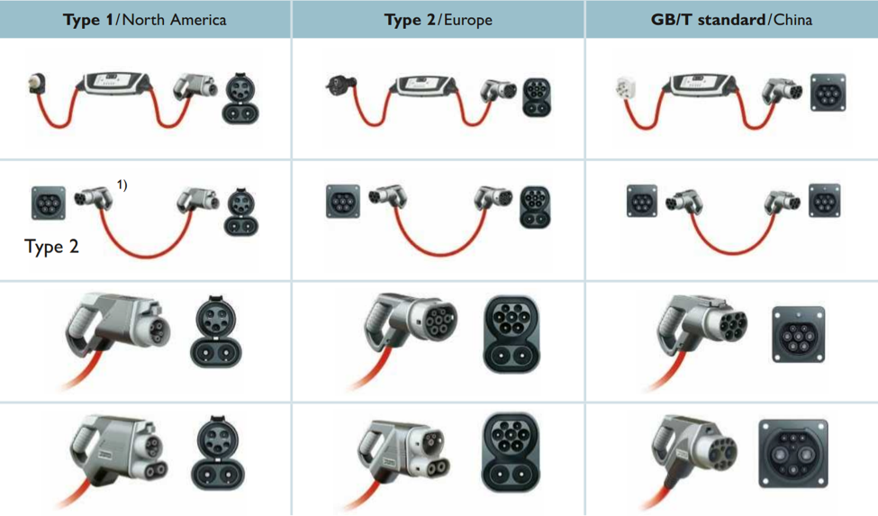
Figure 5: The CCS Type 1, which complies with SAE J1772 and IEC 62196-3, is
used for fast DC charging in the USA. In early 2013, the European Commission specified the use of the CCS Type 2
charging system according to IEC 62196 as a uniform standard throughout Europe. The DC charging system that
complies with the GB/T standard provides fast DC charging for Chinese charging stations in charging mode 4. The
unique locking mechanism is integrated in the vehicle connector and was developed by Phoenix Contact. Source: Phoenix Contact
Phoenix Contact offers the complete range of charging solutions, including connectors from a single source: Type 1,
Type 2, and GB/T standard, as well as charging controllers for every e-mobility application from residential and
commercial, to large, public-use EV charge controllers and beyond to custom solutions.
Summary
The path from the invisible but vital chemistry of battery cells and packs, to the highly visible and tangible
connectors and contacts which route the battery-pack current of EV/HEVs requires careful, extreme attention to many
details and subtleties. Issues which would be minor or modest in portable consumer devices are major ones in these
applications, given the voltages and power levels, the operating environment, and user expectations. Battery-pack
performance under normal extreme conditions, and especially under abnormal conditions, encompassing thermal
management, cell balancing, connector IR drop, and connectors with solid retention but easy disengagement are a few
of the many issues. These must be examined, reviewed, and resolved from many perspectives, with a clear focus on
priorities, tradeoffs, and the interplay between solutions.
References
1. http://www.mouser.com/applications/automotive-hev-main-inverter/
2. http://www.mouser.com/ds/2/256/MAX14920-MAX14921-252827.pdf
3. http://www.mouser.com/pdfdocs/PhoenixContactsolutionsbrochurefore-mobility.pdf
 Bill Schweber is a
contributing writer for Mouser
Electronics and an electronics engineer who has written three textbooks on electronic communications systems,
as well as hundreds of technical articles, opinion columns, and product features. In past roles, he worked as a
technical web-site manager for multiple topic-specific sites for EE Times, as well as both the Executive
Editor and Analog Editor at EDN.
Bill Schweber is a
contributing writer for Mouser
Electronics and an electronics engineer who has written three textbooks on electronic communications systems,
as well as hundreds of technical articles, opinion columns, and product features. In past roles, he worked as a
technical web-site manager for multiple topic-specific sites for EE Times, as well as both the Executive
Editor and Analog Editor at EDN.
At Analog Devices, Inc. (a leading vendor of analog and mixed-signal ICs), Bill was in marketing communications
(public relations); as a result, he has been on both sides of the technical PR function, presenting company
products, stories, and messages to the media and also as the recipient of these.
Prior to the MarCom role at Analog, Bill was associate editor of their respected technical journal, and also worked
in their product marketing and applications engineering groups. Before those roles, Bill was at Instron Corp., doing
hands-on analog- and power-circuit design and systems integration for materials-testing machine controls.
He has an MSEE (Univ. of Mass) and BSEE (Columbia Univ.), is a Registered Professional Engineer, and holds an
Advanced Class amateur radio license. Bill has also planned, written, and presented on-line courses on a variety of
engineering topics, including MOSFET basics, ADC selection, and driving LEDs.
 Singapore


